|
|


EPAC
Home of COLDPLATE Software - The Most Comprehensive Cold Plate Analysis and Design Software on the Planet!
Home of COLDPLATE Software - The Most Comprehensive Cold Plate Analysis and Design Software on the Planet!
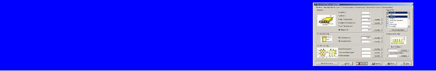
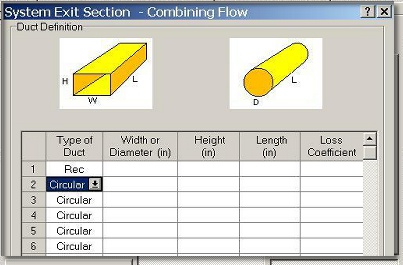
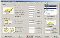
Geometry, Insulation and Bypass Flow Input Image
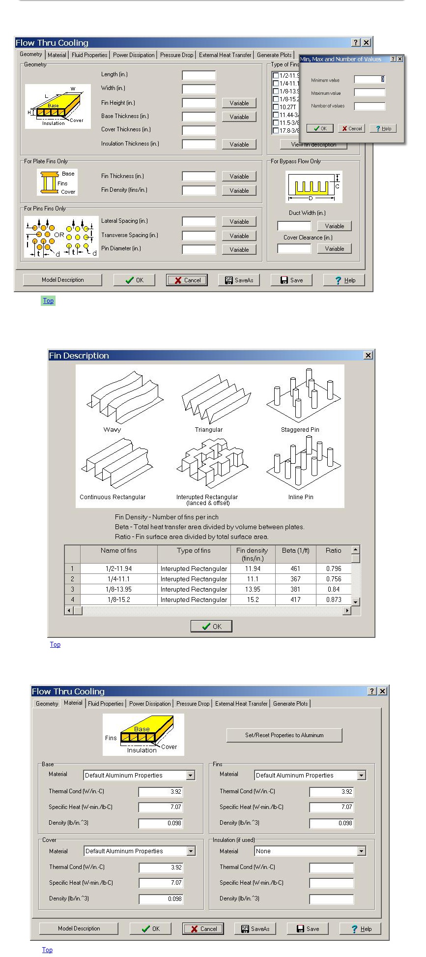
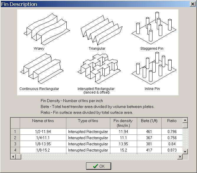
Example of Different Fin Types
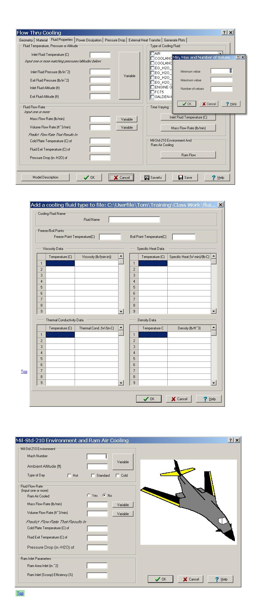
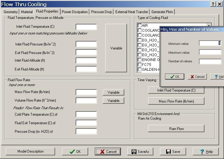
Fluid Selection, Flow Rate and Variable Environment Definition
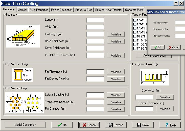
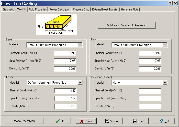
Material Properties Definition
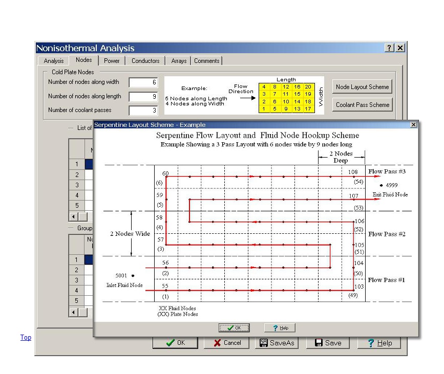
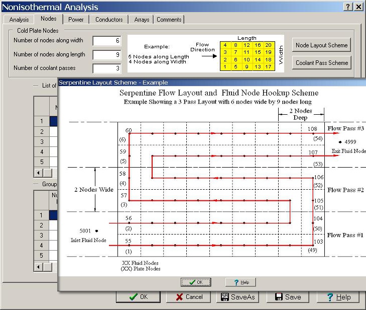
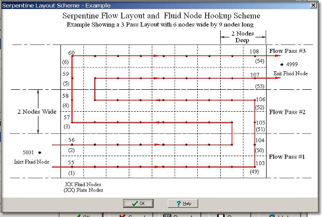
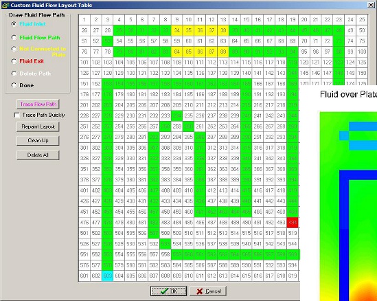
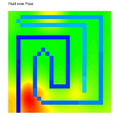
Serpintine Flow Path Images with 3 path example (3 coolant passes)
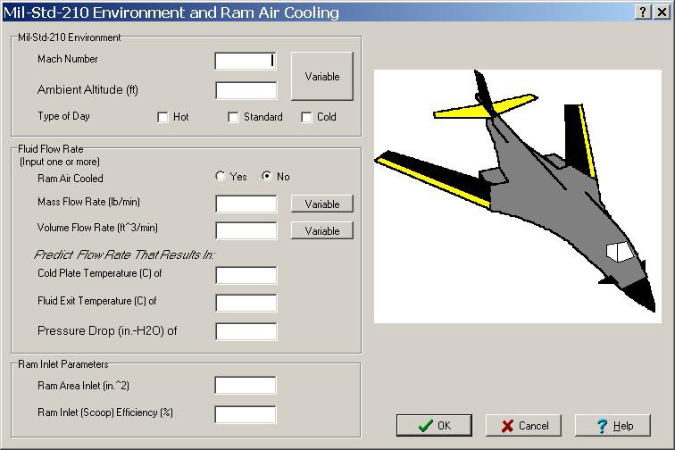
Ram Air Cooling Definition
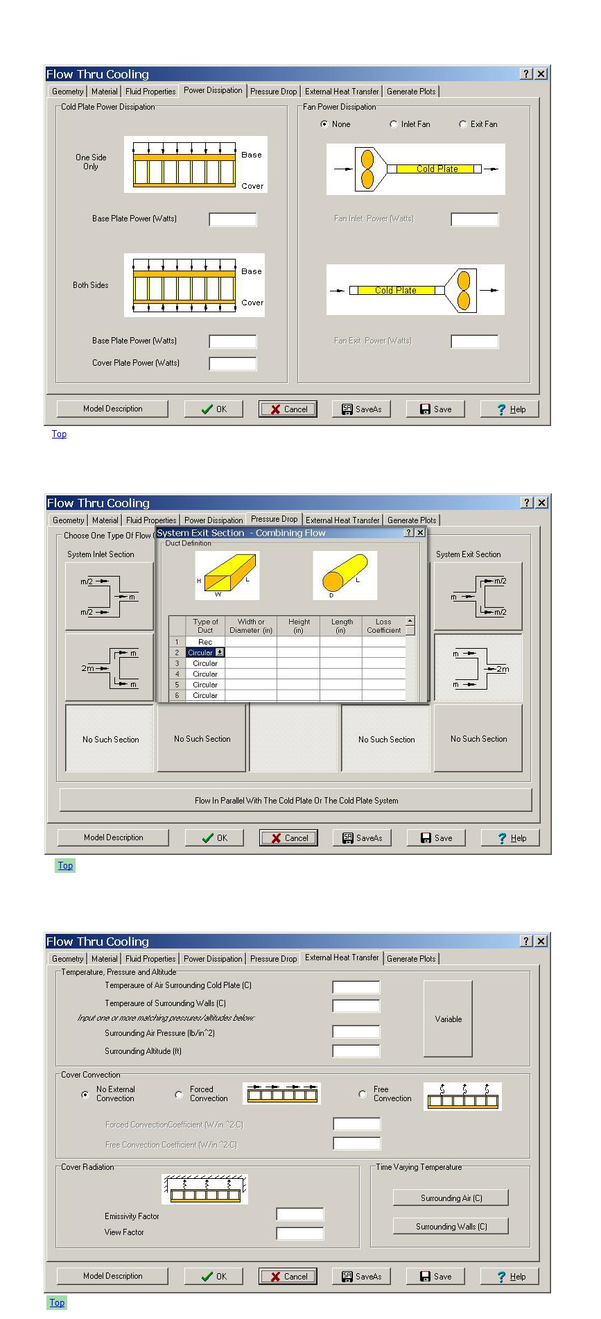
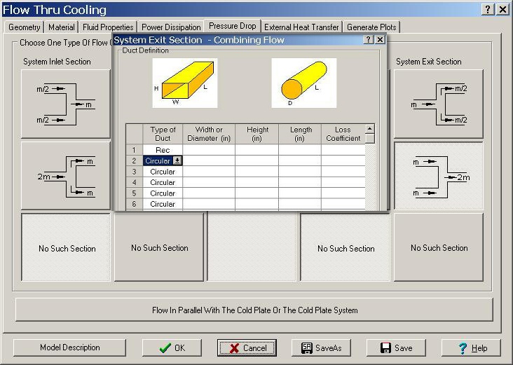
Pressure Drop Parameter Definition
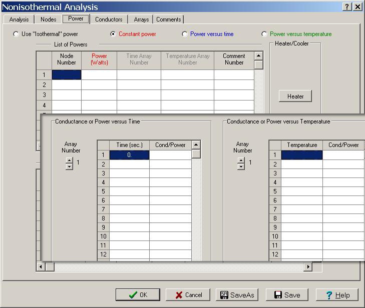
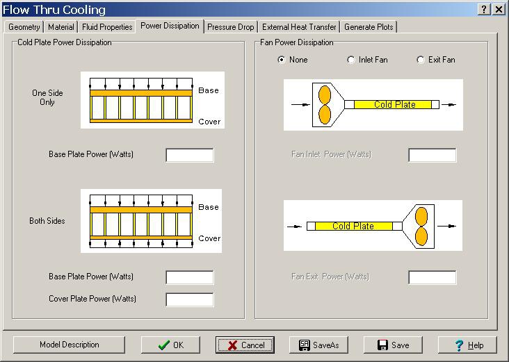
Power Dissipaton Methods
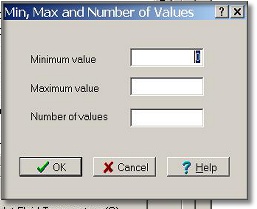
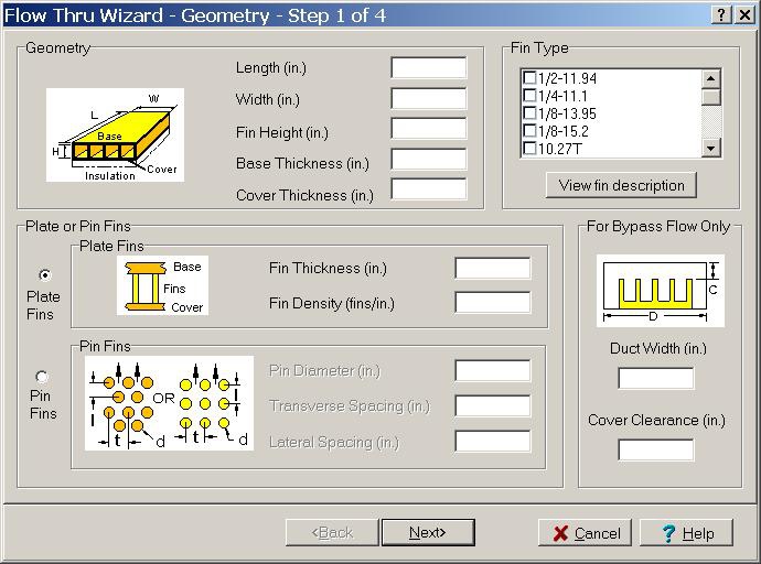
Step 1 of 4 of the Isothermal Temperature Wizard
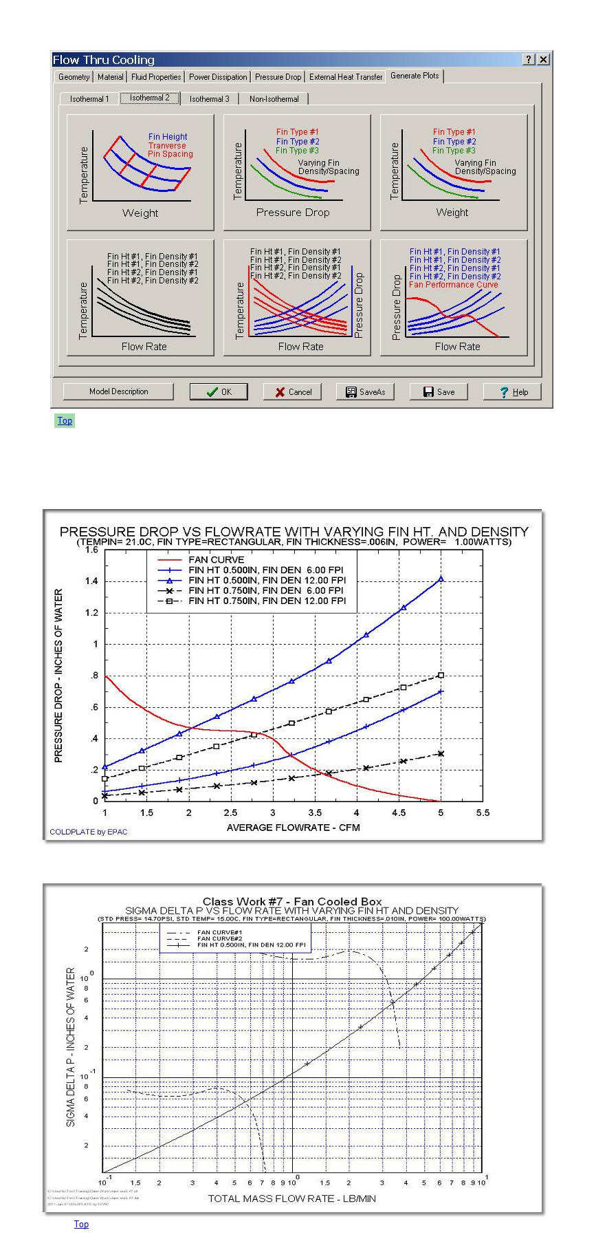
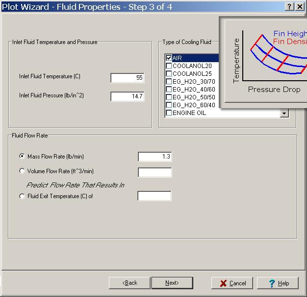
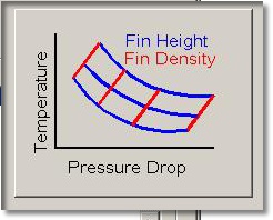
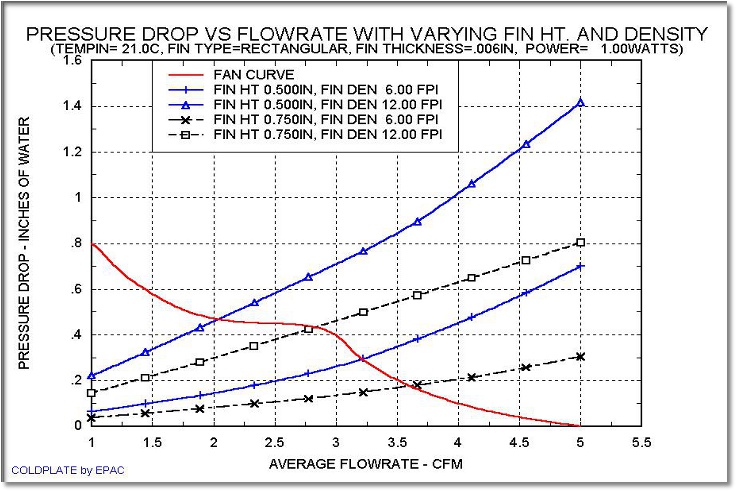
Step 3 of 4 of the Plot Wizard of Variable Fin Height and Fin Density
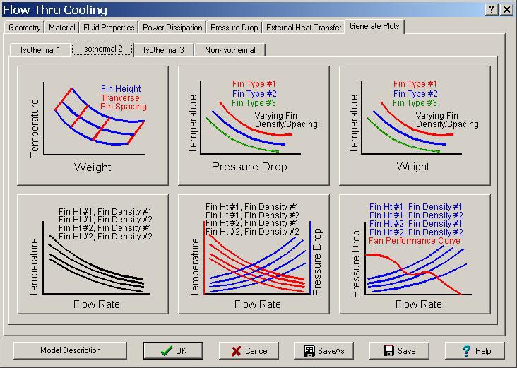
Plot Selection Form
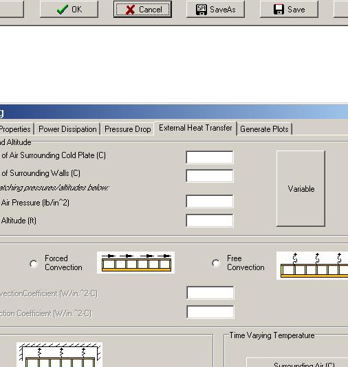
External Heat Transfer - External Convection and Radiation
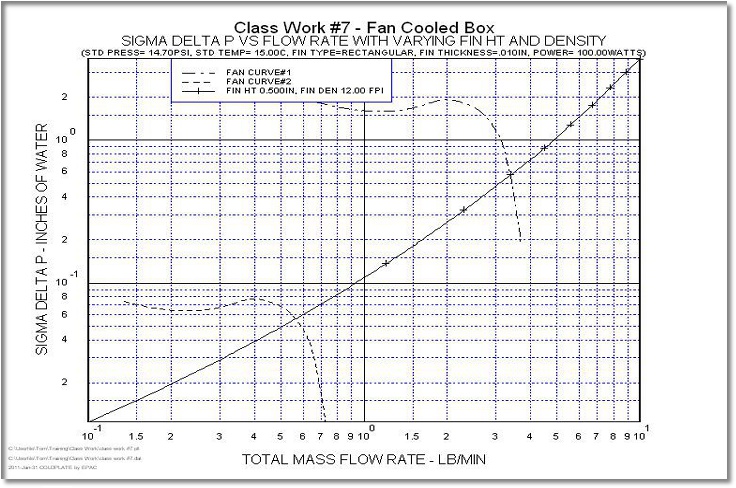
Fan Balancing Example Plots
Fan Balancing Example Plots - Fan Operation at Sea Level and 40KFT
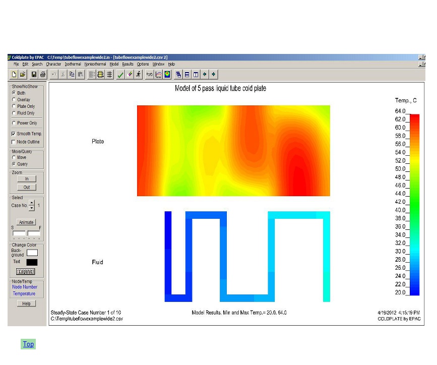
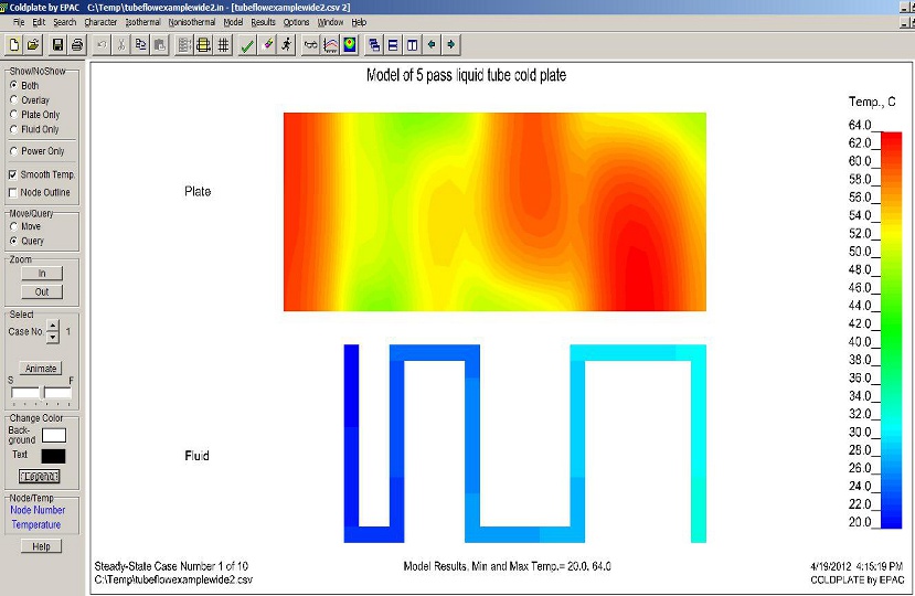
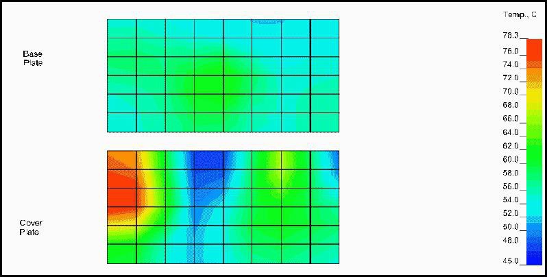
Example Color Contour Plot (5 coolant passes)
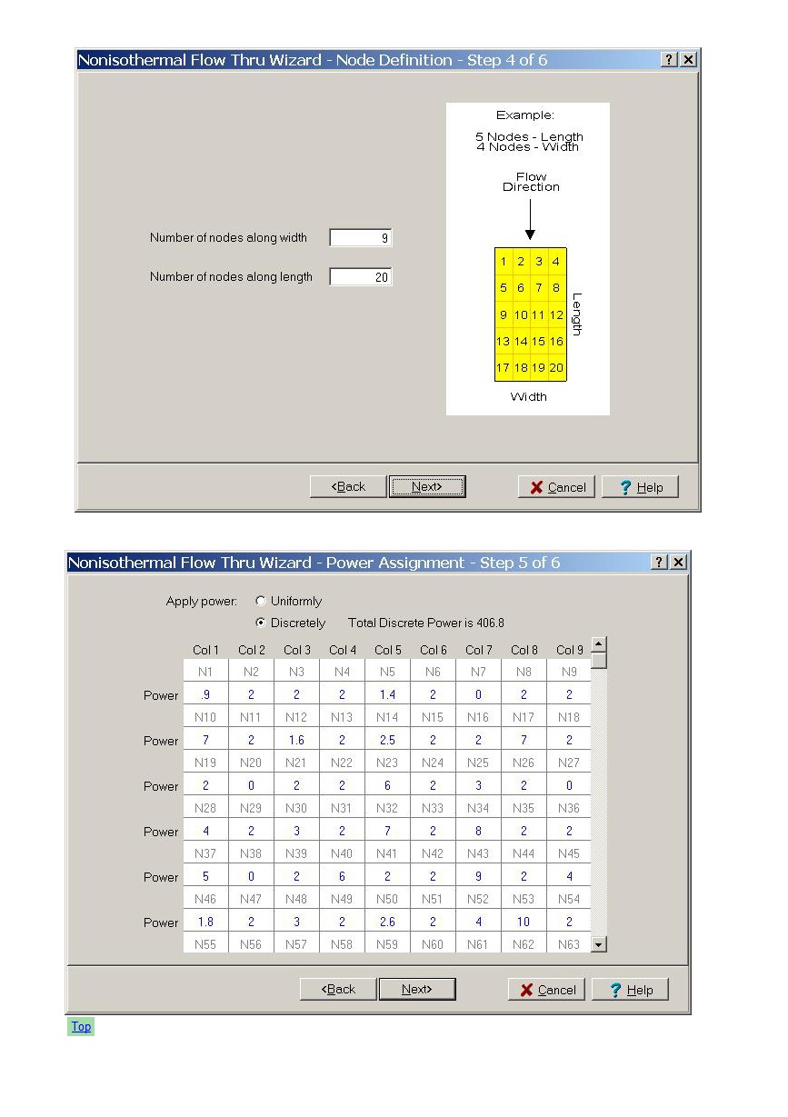
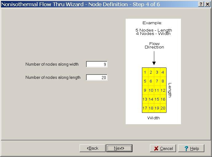
Step 4 of 6 of the Non-isothermal Wizard (9 nodes wide by 20 nodes long)
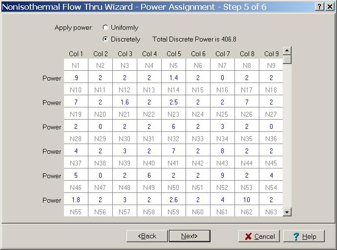
Step 5 of 6 of the Non-isothermal Wizard (power assignment on each node)
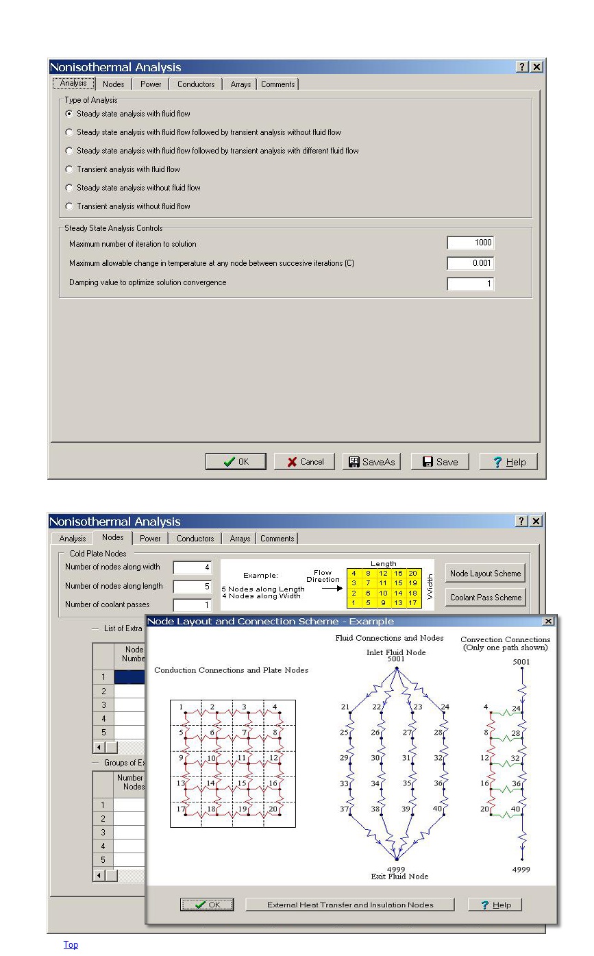
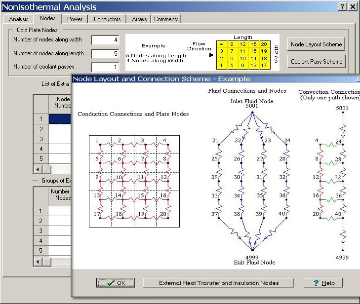
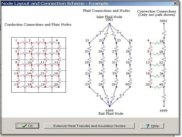
Non-isothermal example of automatically building model 4 nodes 4 by 5 nodes long
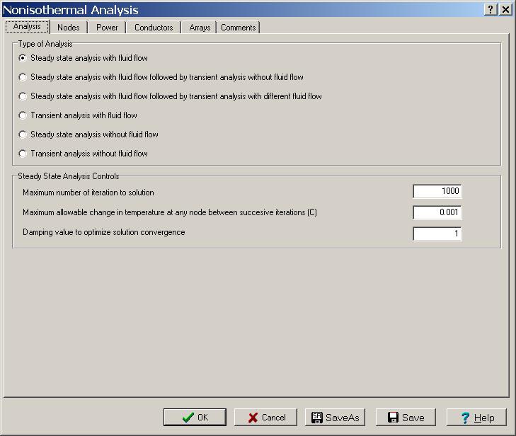
Non-isothermal analyses methods available: steady-state, transient, flow and no-flow
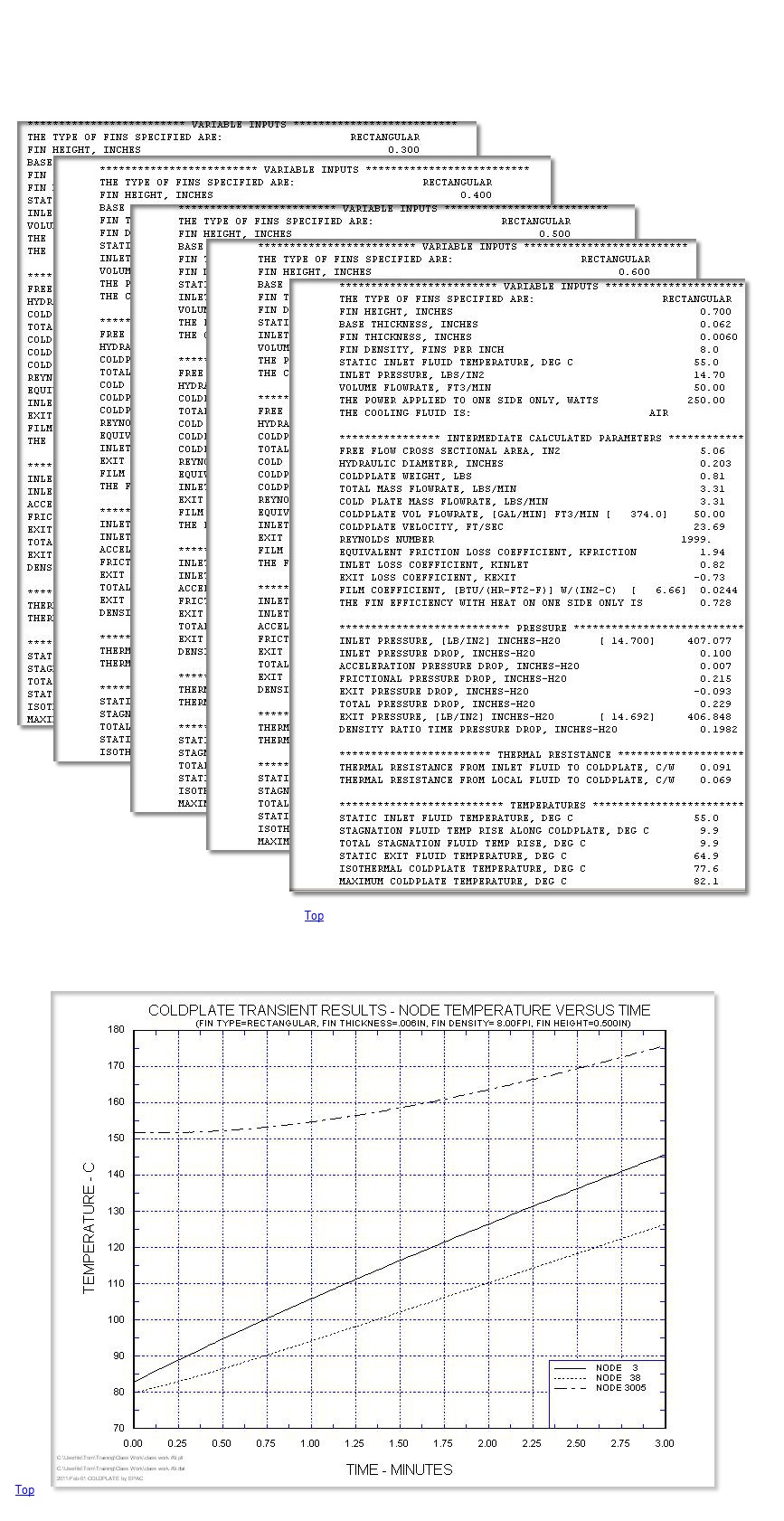
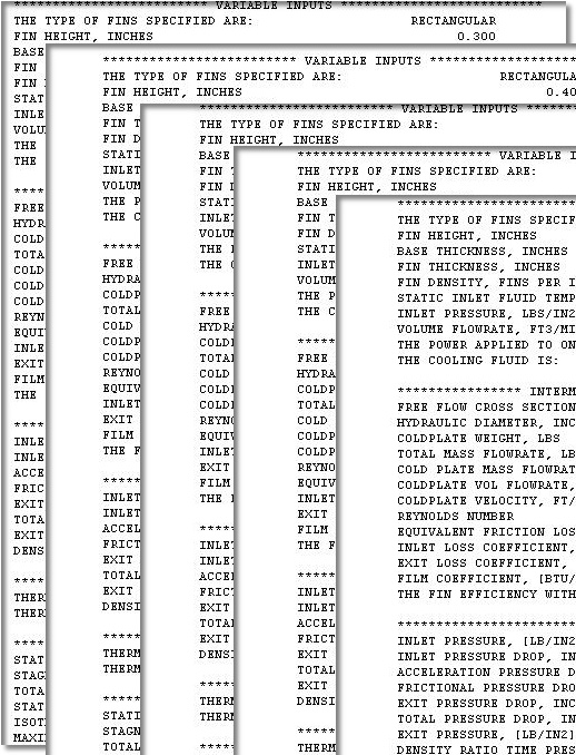
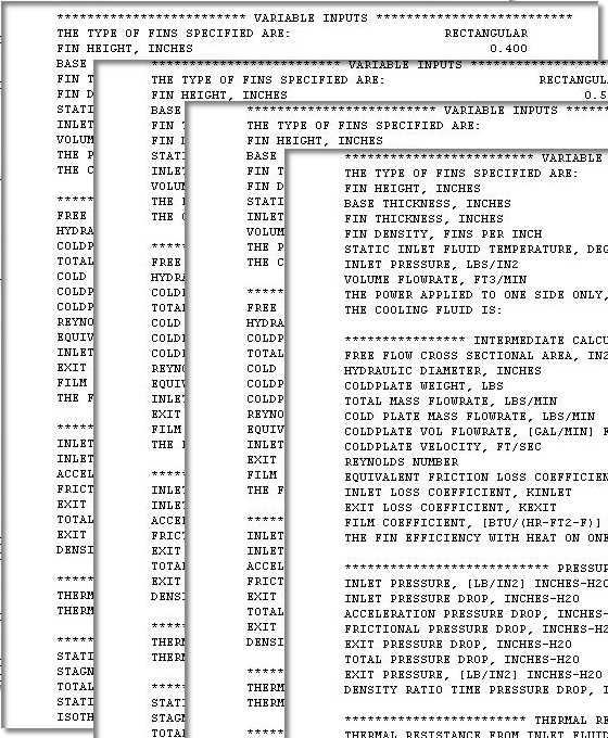
Steady-State Example Results - Varying Fin Height from .3 to .7 inches. All in one run!
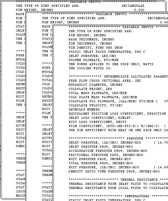
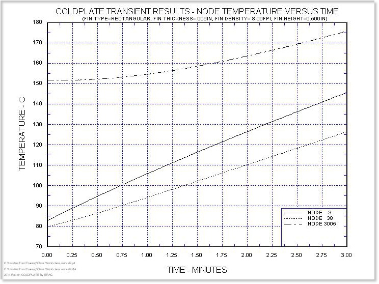
Transient Example Results - Steay-State Analysis followed by Transient with no Fluid Flow
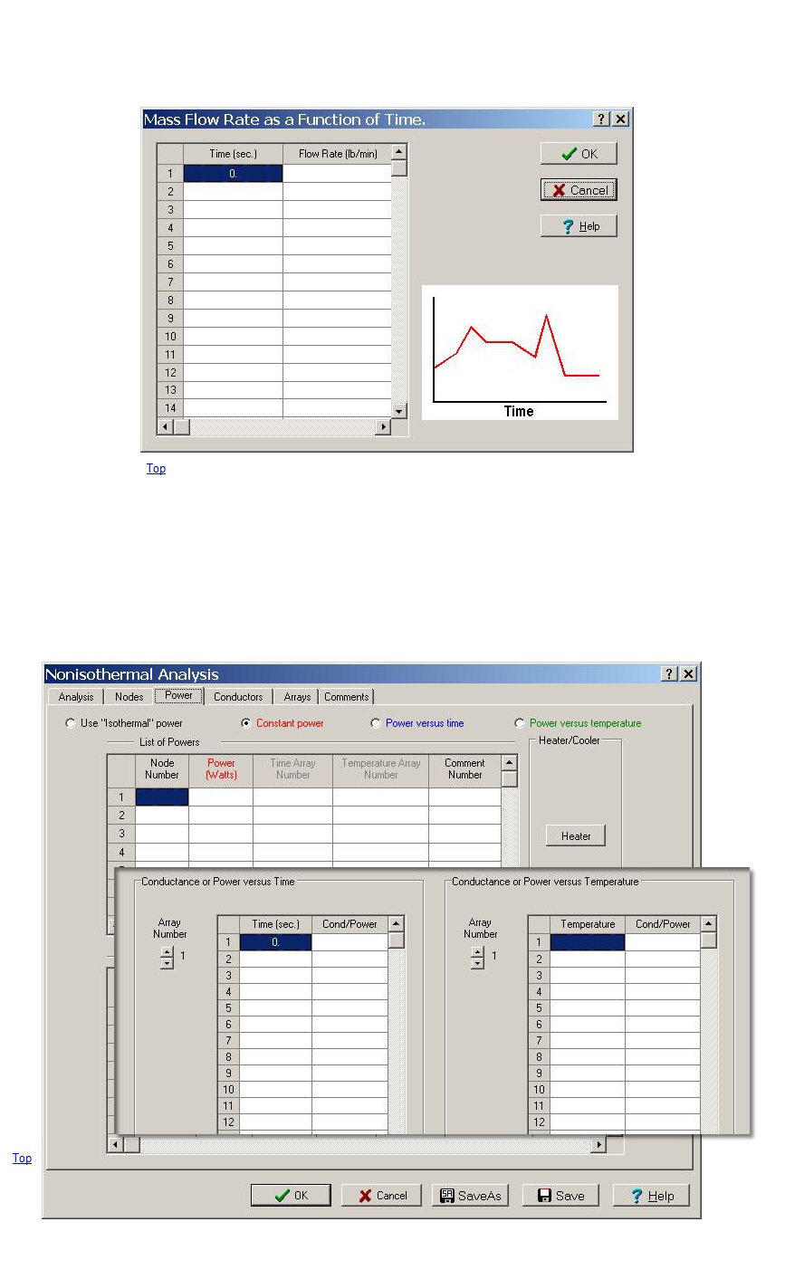
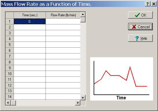
Both Fluid Flowrate and Inlet Fluid Temperature can be input as a function of time
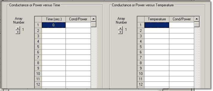
Power and/or Conductors can be functions of time or temperature or constant
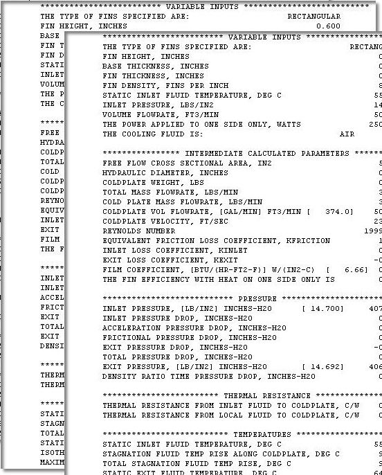
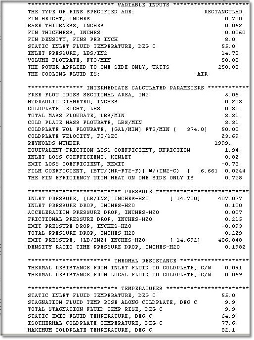
Intermediate (.int file) results showing useful input parameters for CFD or FEM
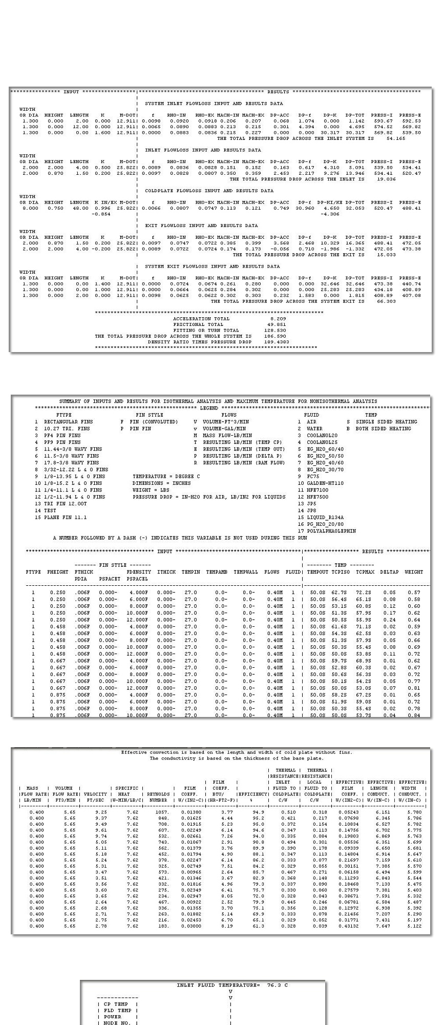
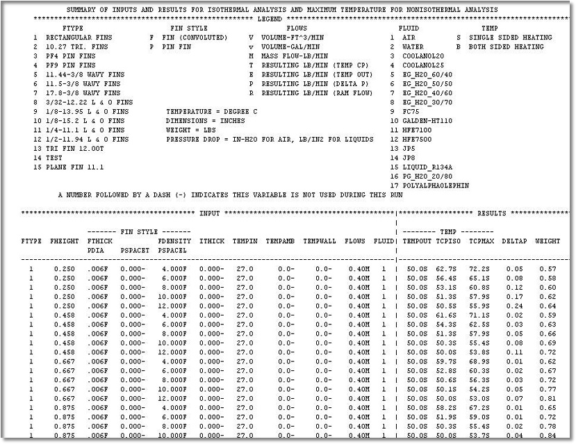
Summary table (.tab file) of results from running a parametric model, in this case varying the
fin height and fin density
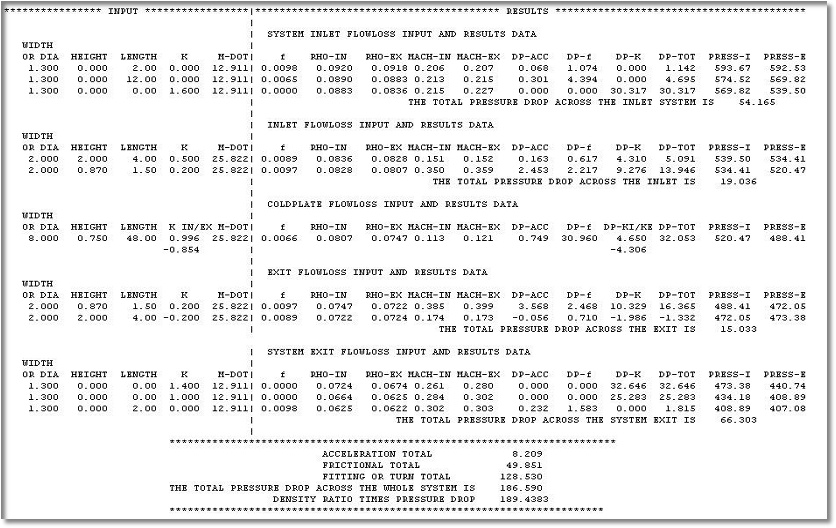
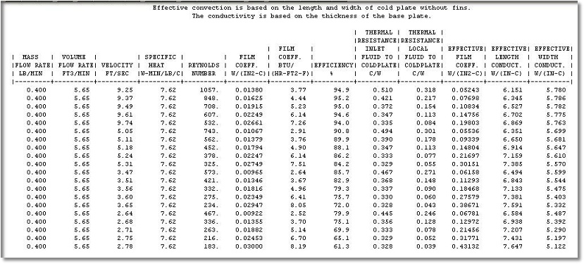
This is the detailed pressure drop output (.dlp) file showing the pressure drop, etc. at each
section.
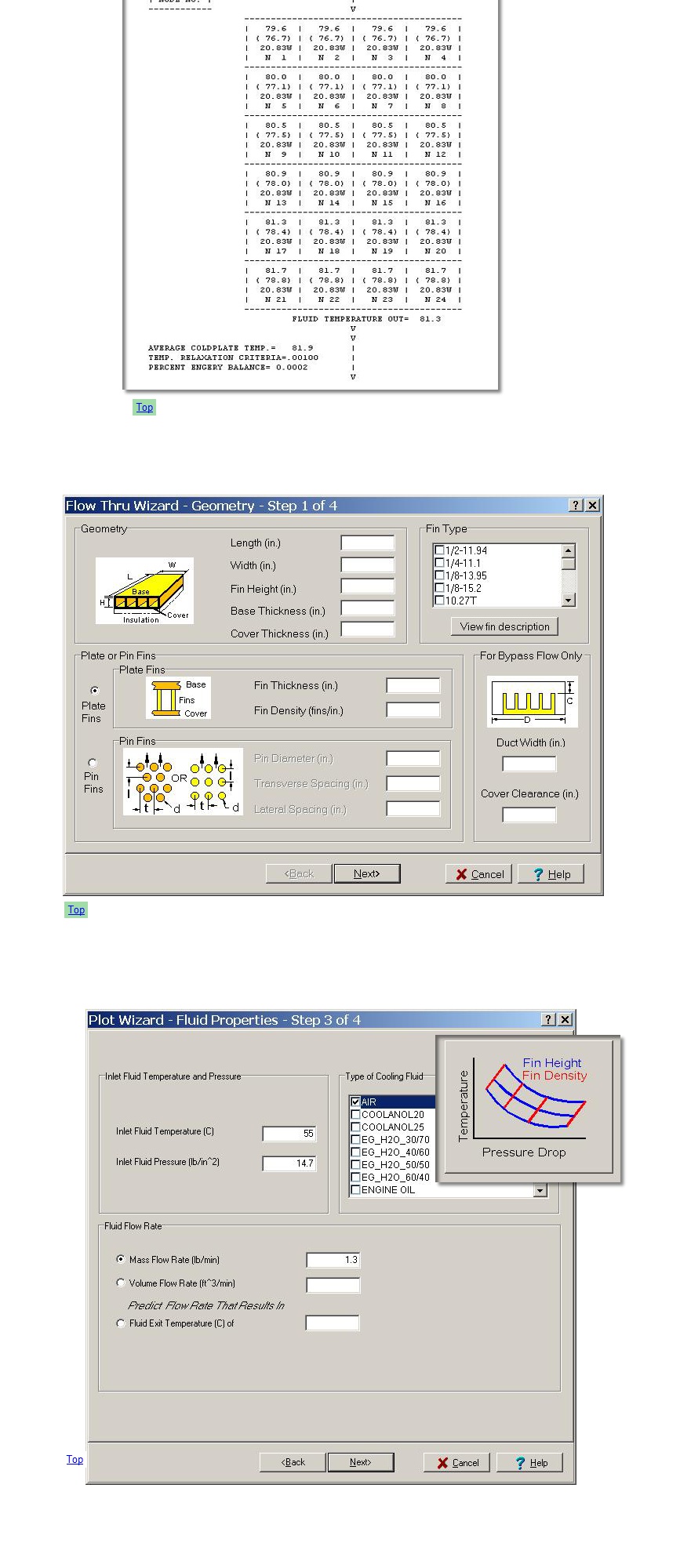
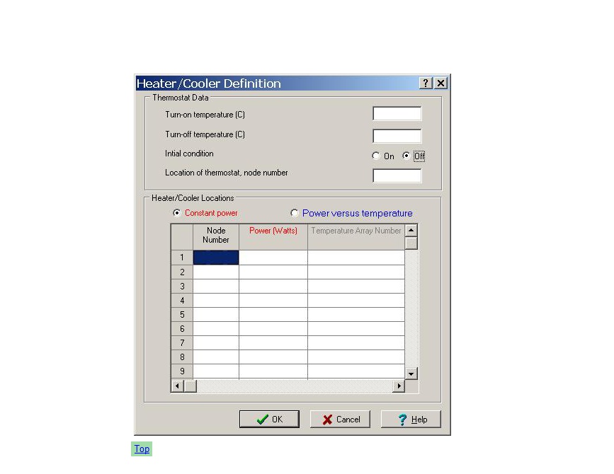
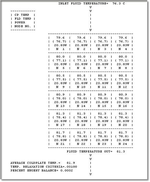
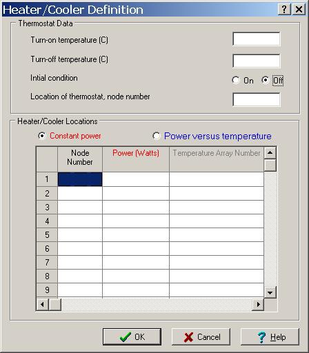
Nonisothermal detailed results (.out) file showing the cold plate, fluid and power at each node.
The power at various nodes can be controlled by the temperature at a master node, a
thermostat location.
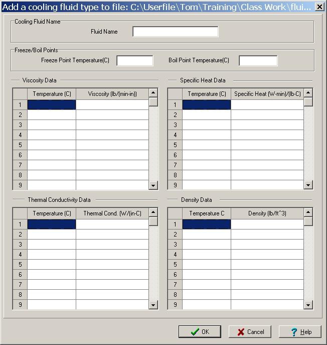
Adding A New Cooling Fluid Not already in the Fluid Library.
Below are shown some of the window images that are part of the COLDPLATE software. Click on any of the links to
see the different images (screen shots).
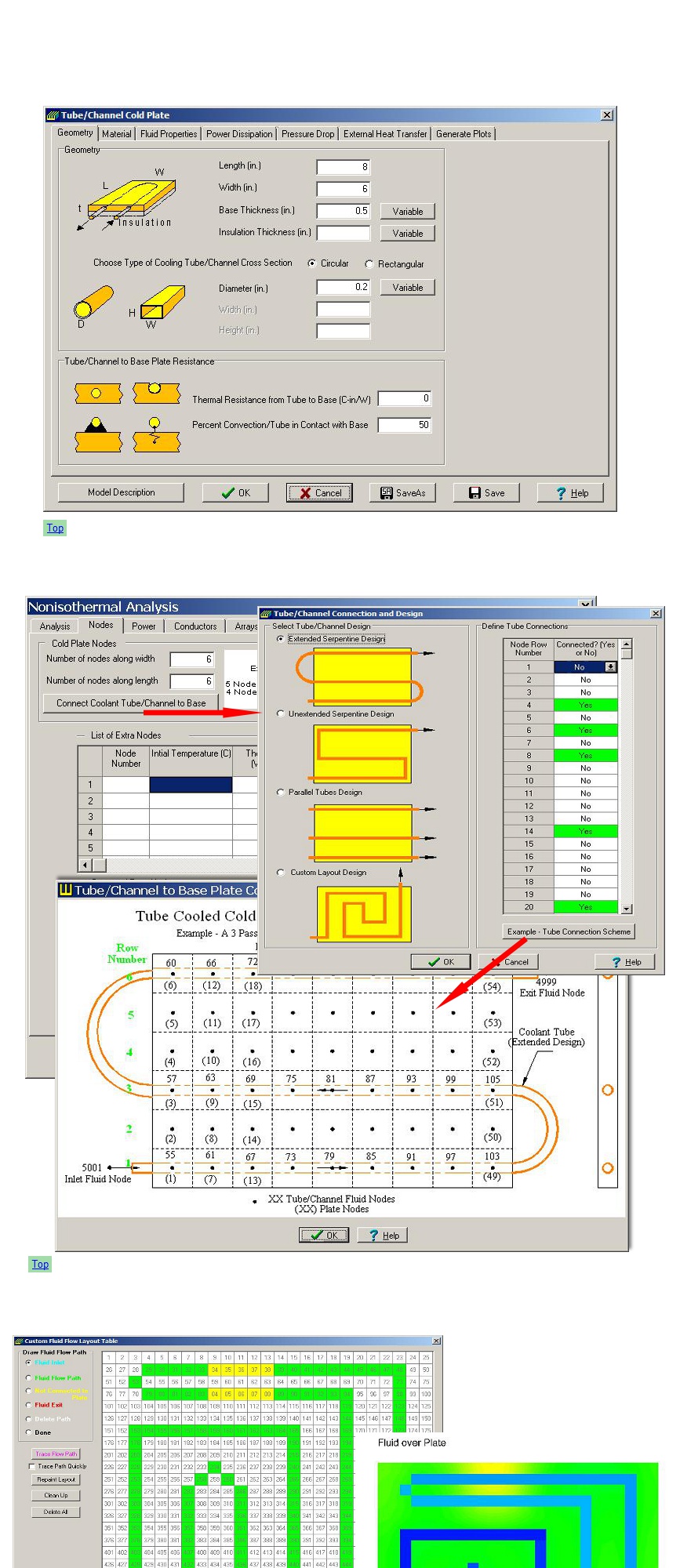
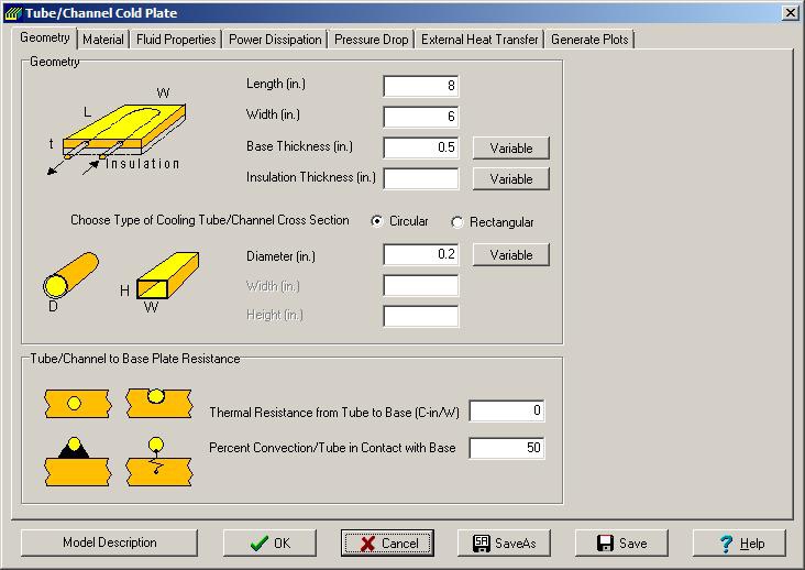
Geometry of Plate, Tube Cross Section and Tube to Plate Resistance
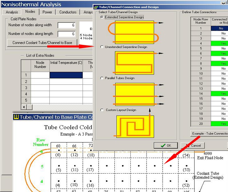
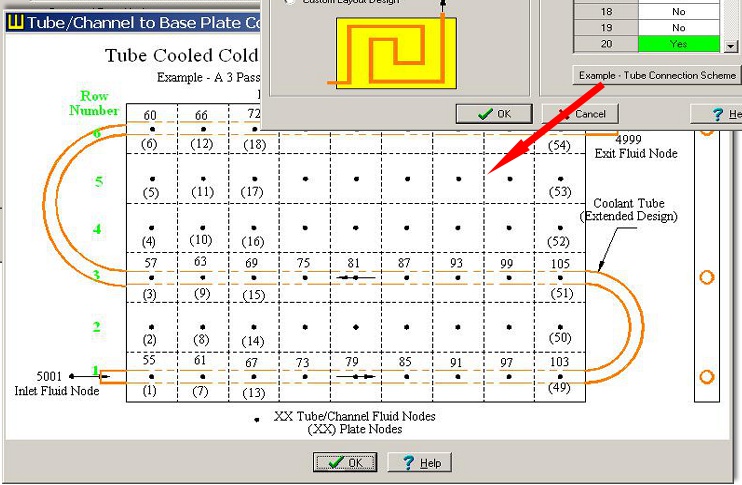
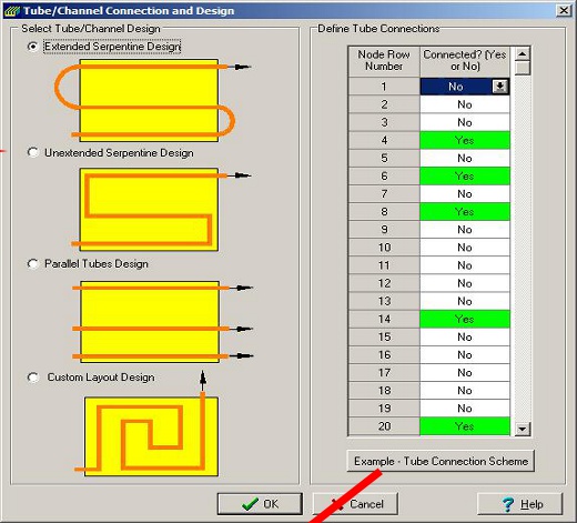
Node Definition and Tube/Channel to Plate Connection
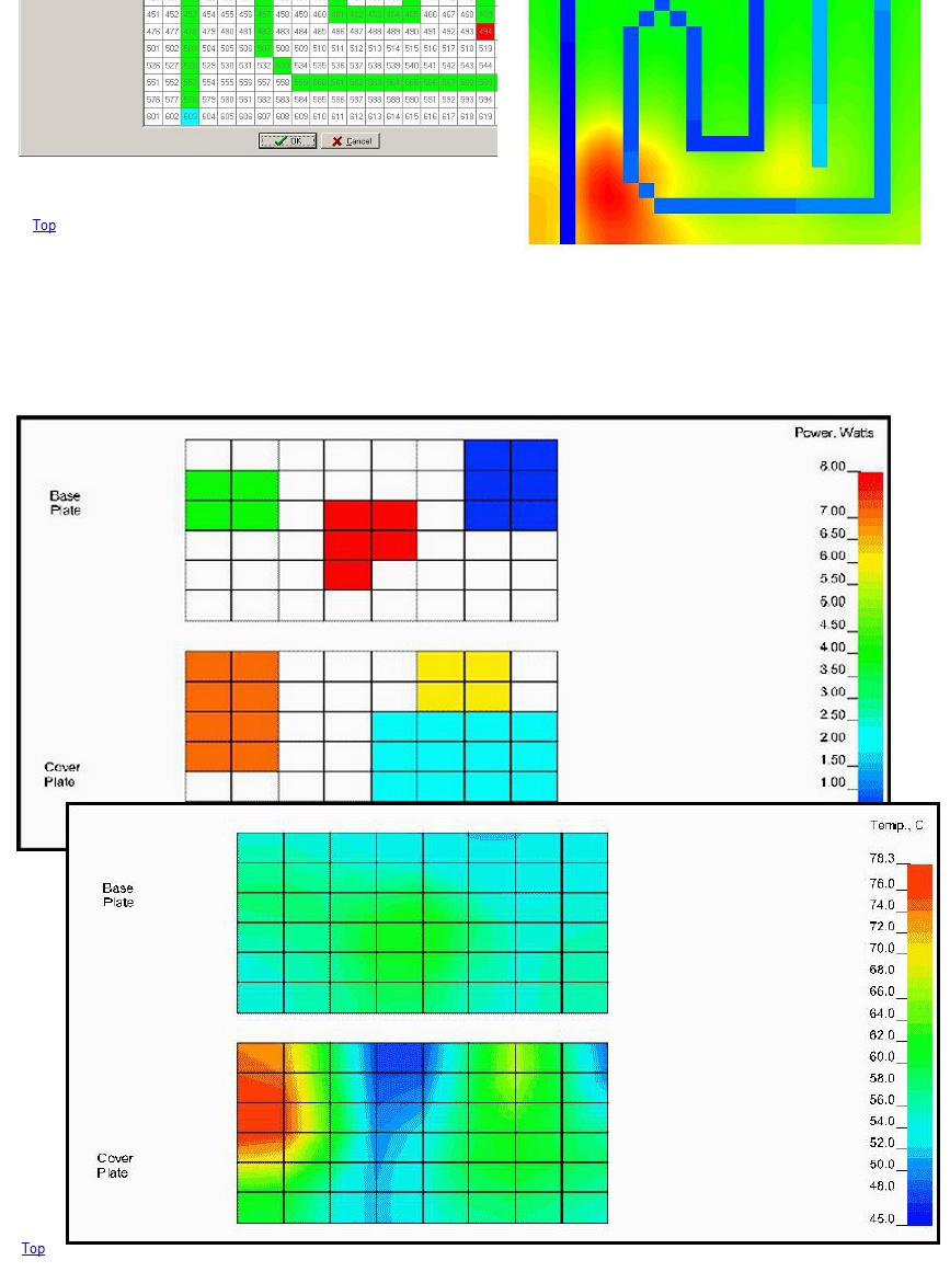
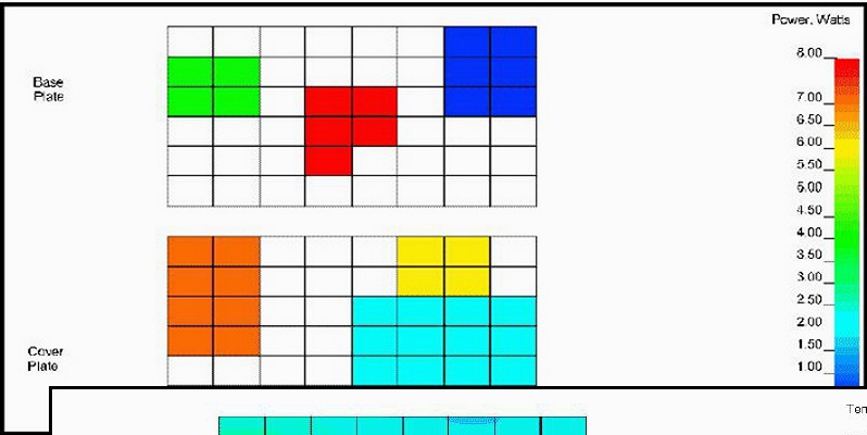
2 Sided Power Dissipation and 3D Temperature Prediction
Tube/Channel Model - Custom Layout and Tube to Plate Connection
Copyright 2019 epac-inc.com