|
|


EPAC
Home of COLDPLATE Software - The Most Comprehensive Cold Plate Analysis and Design Software on the Planet!
Home of COLDPLATE Software - The Most Comprehensive Cold Plate Analysis and Design Software on the Planet!
Introduction
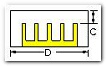
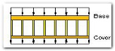
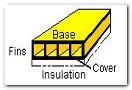
Cold plate thermal analysis software from EPAC offers user friendly design and analysis of cold plates and heat sinks. A cold plate is a heat sink with a cover on it to force air or a liquid between the fins and enhance the heat transfer. Simply put, lift the cover off the cold plate and you have a heat sink.
COLDPLATE offers rapid analysis, design, and presentation of trade studies involving different fin parameters, geometry, fluid flow rates and boundary conditions for cold plates and heat sinks. With COLDPLATE, both isothermal and non-isothermal analysis can be performed within minutes, try that with CFD.
Fin height, fin density (number of fins per inch), fin thickness and base plate thickness, pin fin diameter and pin fin spacing all may have variable values within the same model allowing easy parametric analyses to be performed.
Numerous types of longitudinal fins may be modeled
from a built in database. In addition, fin types defined
by the user can be added to the fin type library.
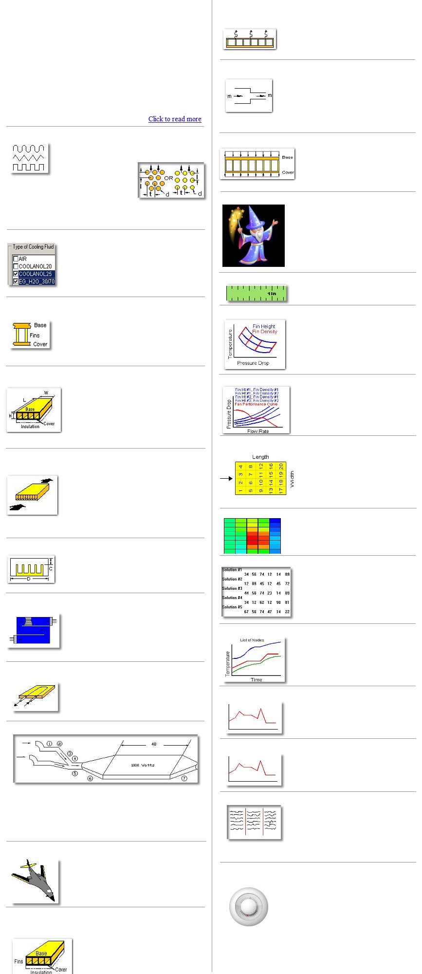
In addition to modeling air as the cooling/heating fluid there is an extensive library of fluids available for modeling. The user may also add their own fluids to the library. In addition, COLDPLATE allows the user to specify more than one fluid type within the same model.
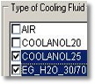
Both in-line and staggered
pins may also be modeled.
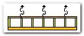
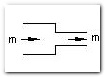
The flowrate of fluid through the cold plate can be defined by a number of methods. They include defining the mass flow rate, the volume flow rate, the desired cold plate temperature, the desired exit fluid temperatur, the disired pressure drop across the cold plate or ram air velocity . Each of these option may also be independently defined and a number of them may have variable input values.
Any number of different fin types may be specified within the same
mode allowing parametric analyses to evaluated.
Fin Types
Fluid Types
Variable Geometry
Variable Environments
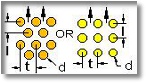
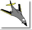
Ram Air Flow
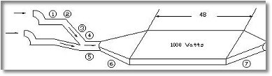
COLDPLATE Ram air cooling describes a process/analysis whereby
air is ingested into a scoop or opening that leads to a cold plate.
The scoop/opening and cold plate are usually a part of an moving
vehicle (aircraft, missile, pod or automobile). The pressure build
up in front of the scoop or opening is what causes air flow into the
cooling system.
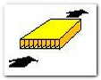
Bypass Flow
Air that flows over and through a heatsink but is
not contrained to have all the air go between the
fins may easily be accounted for by defining the
space around the heatsink.
Material Properties
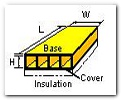
The cold plate/heatsink base plate, fins, cover and optional insulation do not have to be made of the same material. The thermal conductivity, density and specific heat each part may be independently defined. In addition, there is library of materials of these properties which may be edited by the user.
Any type of conditions such as land, sea or air may be modeled. Fluid flow inlet temperature, pressure or altitude conditions can input as a single value or as an array of values to simulate aircraft flight conditions or ground conditions at different locations.
Flowrate Options
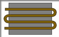
Serpentine Flow Path
Not only can you model a finned cold plate with a
straight through flow path, but a multi-turn flow
path cold plate can also be modeled and analyzed.
All it takes is inputting a single value of the
number of truns the flow path makes.
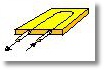
External Convection and Radiation
Heat transferin the form of convection or
radiation external to the cold plate may be
accounted for by specifying the ambient air or
wall temperature.
Pressure Drop Parameters
Full accounting of turn losses, area change
lossess, friction losses or other type of
pressure drop losses both before and after
the cold plate are calculated by COLDPLATE
and added to the internal pressure drops
within the cold plate.
Power Application
Power may be applied to the base
of the cold plate or to both the
base and cover.
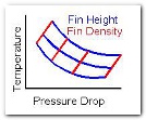
Numerous plots of results can be
easily generated and displayed.
Parametrice trade studies of fin
height, fin density, fin thickness,
flluid flow rate, temperature versus
time, etc are just some of the type
of plots available.
Plots of Results
Insulation from Ambient
To protect the cold plate from heat infiltration (heat transfer) from a hot ambient, an isulation layer mounted on the cover may be modeled by specifying its thickness, thermal conductivity, density and specific heat. Additionally, the thickness can be a variable parameter to allow quick assessment of its benefit.
Wizards
Four different modeling wizards are
available to speed up building of models.
One wizard generates a simple model
within minutes for the new user. Two of
the other wizards generate models to
generate plots of numerous parametric
trade studies and the last one walks the
user through building non-isothermal
models.
Units Selection
Both SI and English units are
available.
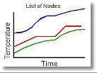
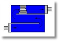
Fan Balancing
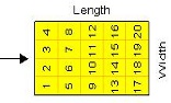
The cold plate can automatically be
divided into nodes (finite difference
method) to predict the temperatures
across the cold plate. All that is
needed is specification of the number
of nodes along the width and length.
Non-isothermal Analysis
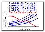
Fan performance curves may be
input and its operating point(s) may
be determined using the flow rate
variable input capability.
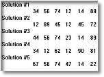
Steady-state temperature prediction
with or without fluid flow can be
performed. For each variable
parameter input, a seperate analysis is
performed. For example, if 5 different
fin height are input, then 5 different
predictions are made.
Steady-State
Transient analysis is also a solution
feature of COLDPLATE. Modeling can
consist of a steady-state analysis then
followed with a transient analysis
including fluid flow or no fluid flow
conditions.
Transient Analysis
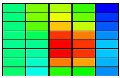
Color contour plots of the cold plate and
fluid can be easily generated giving the
user insight and understanding of their
design.
Contour Plot
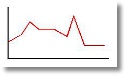
Environment versus Time
The inlet fluid temperature or fluid flow
rate may be a constant value or may be a
time varying value.
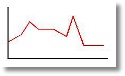
Power or Conductances vs Time or Temperature
The power at each node or conductances
between nodes may a constant value or may
be a time or temperature varying value.
Thermostat Modeling
A temperature controlled heater or cooler can
be modeled as part of the non-isothermal cold
plate analysis. The heater/cooler is controlled
by inputting the sensed node number, the on
and off temperature, the the initial switch
position and a list of nodes and their
corresponding power.
Results Files
There are a number of results files
generated with each analysis. The files
specialize in the type of results presented:
intermediate results, summary of
parametric studies, detailed pressure drop
results, Excel readable file of results, etc.
Flow may be modeled through a circular or
rectangular tube that follows a serpentine path.
The tube or channel connections to the base plate
is automatically assigned via node row numbers.
Tube/Channel Cold Plate
Copyright 2019 epac-inc.com