|
|


EPAC
Home of COLDPLATE Software - The Most Comprehensive Cold Plate Analysis and Design Software on the Planet!
Home of COLDPLATE Software - The Most Comprehensive Cold Plate Analysis and Design Software on the Planet!
Cold plate analysis design is a snap using COLDPLATE thermal modeling and simulation software. COLDPLATE from EPAC offers user
friendly design and analysis of cold plates and heat sinks. Numerous types of cold plates and heat sinks are easy modeled without having
to spend valuable time using CFD (Computational Fluid Dynamics) or FEM (Finite Element Modeling) code on design iterations. Use
COLDPLATE to do your preliminary analysis to quickly zero in on your design before committing to more detailed analysis. In many cases,
COLDPLATE is all you need for your design and analysis.
Extended Multi-Pass Tube Model
Large Selection of Fin Types Modeled, Including Pin Fins
Conventional Flow Through Finned Models
The program performs heat transfer and pressure drop analyses of cold plates and heat sinks, it offers rapid thermal analysis and
presentation of trade studies including different fin parameters (variable height, density, thickness), fin types, base thicknesses, fluid flow
rates, fluid types and boundary conditions and much more. Both isothermal and non-isothermal heat transfer analysis using an integrated
finite difference routine can be performed within minutes compared to CFD or FEM.
Model size (number of nodes and nodal connections) is controlled by the user by merely changing a single parameter. There is no need to redefine the geometry. Conversely, the geometry (length, width, etc.) and other parameters such as flow rates and fluid types can be changed without redefining the model size. For example, if you want to increase the fin thickness, just change it to a new value and the model fin spacing, Reynolds number, nodal interconnections, conductions, etc. are all updated automatically and the model is ready to run.
Nodal interconnections: convection, advection (one-way conductors), conduction and radiation within the cold plate are all automatically calculated and assigned. And of course, power assignment can be either uniform or non-uniform, steady-state or transient. Solutions can consist of either steady-state or transient fluid flow rate analyses or a combination of either.
Simple additional structure can be added to the cold plate/heat sink to model components, circuit cards, interface resistance or other electronic elements. All of the varying fin parameters, flow rates and boundary conditions are still available with the non-isothermal analyses.
Pressure drop parameters prior to, within or after the cold plate can be added to the model. These parameters may be duct size, duct length and loss coefficients. The allowable system pressure drop can be input and the program will determine the resulting flow rate. A fan or pump curve can be inputted along with variable flow rates to determine the fan or pump or operating point.
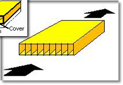
Both detailed and summary results of temperatures, thermal resistances, pressure drops and many other parameters are determined. The results can be presented by numerous automated graphical formats that allow quick and easy selection of the optimum design. For example, in only a few minutes, a model of a cold plate with varying fin height and fin density can be constructed, run and then displayed on a plot showing the resultant temperatures and pressure drops as a function of fin height and density.
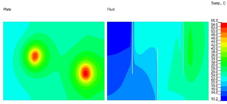
In addition, to text and XY plots of results, color contour plots are displayed showing cold plate and fluid temperatures and power assignments. Animation of temperatures for transient analyses and case number analyses (variable fin height, density, etc.) can also be displayed.
Results from COLDPLATE software have been proven to be accurate through years of testing and verification. However, when the heat sink or cold plate is part of a larger more complex system, results from the COLDPLATE model can be used to select a preliminary design configuration before constructing a model in more detail using CFD, FEM or finite differencing programs. In addition, film coefficients, flow rates, or thermal resistances from the COLDPLATE model can be used as inputs for the more detailed models. Very significant time savings can be realized using EPAC's software as a preliminary tool before committing to constructing these detailed models.
COLDPLATE has been used successfully to model cold plates and heat sinks used on high performance air craft, ships, submarines, computers and commercial equipment. Extruded, machined, cast, welded, brazed or bonded cold plates and heat sinks are easily modeled. Heat sinks used for cooling components on circuit cards can be analyzed using the bypass flow capability. Cold plate analysis models can be generated in minutes by both design engineers and analysts. Learning to use the program requires only a few hours investment of time which then allows the designer or analyst to use the powerful capability of this easy to use tool.
Model size (number of nodes and nodal connections) is controlled by the user by merely changing a single parameter. There is no need to redefine the geometry. Conversely, the geometry (length, width, etc.) and other parameters such as flow rates and fluid types can be changed without redefining the model size. For example, if you want to increase the fin thickness, just change it to a new value and the model fin spacing, Reynolds number, nodal interconnections, conductions, etc. are all updated automatically and the model is ready to run.
Nodal interconnections: convection, advection (one-way conductors), conduction and radiation within the cold plate are all automatically calculated and assigned. And of course, power assignment can be either uniform or non-uniform, steady-state or transient. Solutions can consist of either steady-state or transient fluid flow rate analyses or a combination of either.
Simple additional structure can be added to the cold plate/heat sink to model components, circuit cards, interface resistance or other electronic elements. All of the varying fin parameters, flow rates and boundary conditions are still available with the non-isothermal analyses.
Pressure drop parameters prior to, within or after the cold plate can be added to the model. These parameters may be duct size, duct length and loss coefficients. The allowable system pressure drop can be input and the program will determine the resulting flow rate. A fan or pump curve can be inputted along with variable flow rates to determine the fan or pump or operating point.
Both detailed and summary results of temperatures, thermal resistances, pressure drops and many other parameters are determined. The results can be presented by numerous automated graphical formats that allow quick and easy selection of the optimum design. For example, in only a few minutes, a model of a cold plate with varying fin height and fin density can be constructed, run and then displayed on a plot showing the resultant temperatures and pressure drops as a function of fin height and density.
In addition, to text and XY plots of results, color contour plots are displayed showing cold plate and fluid temperatures and power assignments. Animation of temperatures for transient analyses and case number analyses (variable fin height, density, etc.) can also be displayed.
Results from COLDPLATE software have been proven to be accurate through years of testing and verification. However, when the heat sink or cold plate is part of a larger more complex system, results from the COLDPLATE model can be used to select a preliminary design configuration before constructing a model in more detail using CFD, FEM or finite differencing programs. In addition, film coefficients, flow rates, or thermal resistances from the COLDPLATE model can be used as inputs for the more detailed models. Very significant time savings can be realized using EPAC's software as a preliminary tool before committing to constructing these detailed models.
COLDPLATE has been used successfully to model cold plates and heat sinks used on high performance air craft, ships, submarines, computers and commercial equipment. Extruded, machined, cast, welded, brazed or bonded cold plates and heat sinks are easily modeled. Heat sinks used for cooling components on circuit cards can be analyzed using the bypass flow capability. Cold plate analysis models can be generated in minutes by both design engineers and analysts. Learning to use the program requires only a few hours investment of time which then allows the designer or analyst to use the powerful capability of this easy to use tool.
General overview
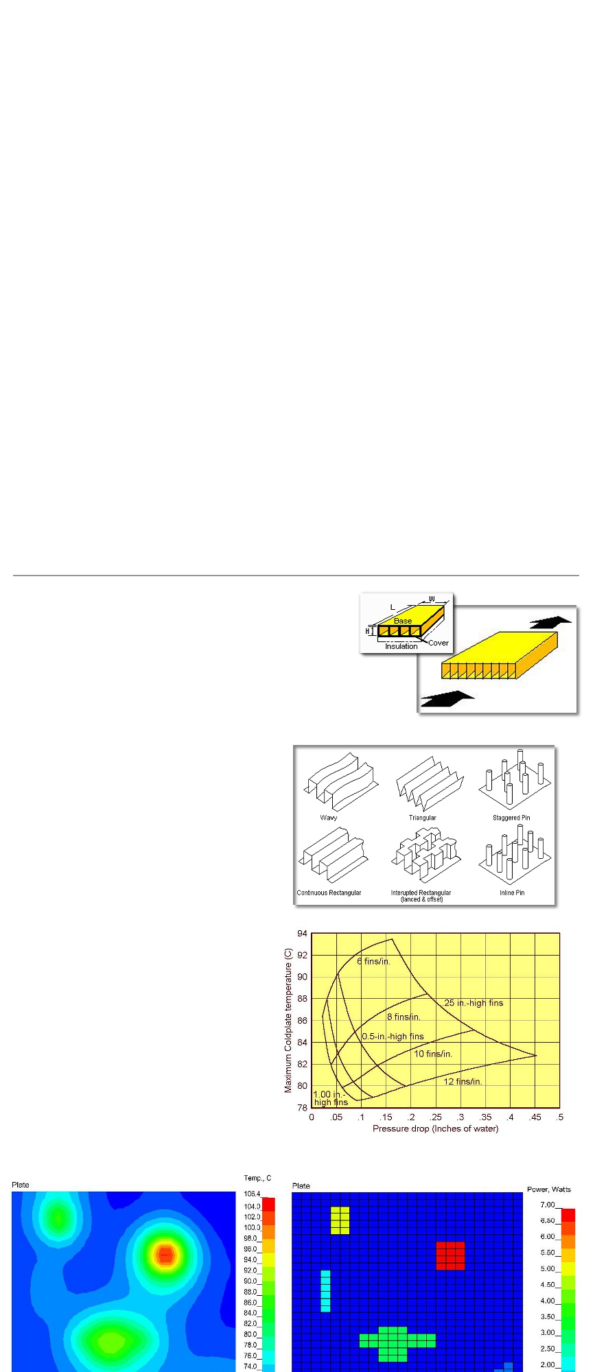
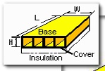
Finned Flow Through models assume that the cooling or heating fluid passes
directly through fins attached to a base plate and cover. Changes in the fluid
pressure, density and temperature prior to entering the cold plate or after the
cold plate may be modeled. Convection to an external ambient via convection
and/or radiation may also be included to simulate heat infiltration. In addition,
an insulating layer of nodes can automatically added to the cover, just select the
material from the material database.
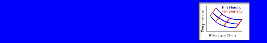
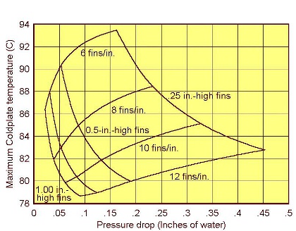
If you need to optimize your design there a number of built in XY
plots available to help zero in on your final design. Using the Plot
Wizard will walk you through a complete model building process,
all you have to do is run the model and then call up the plot
results to display your results. The example shown here shows
temperature and pressure results with varying fin height and fin
density
This model is the same as the Extended Multi-pass cold plate, but generally reflects a machined design. With this model, the section of tube or channel that is within the base plate takes part in heat transfer, i.e. it is attached to the base plate. To change from an extended model to an un-extended model, all that is needed is to chick on a different radio button, everything else remains the same.
Finned Serpentine Model
Bypass Cooled Heat Sink Model
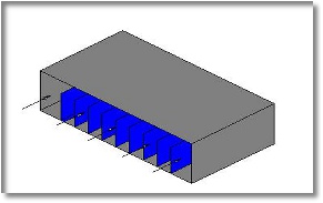
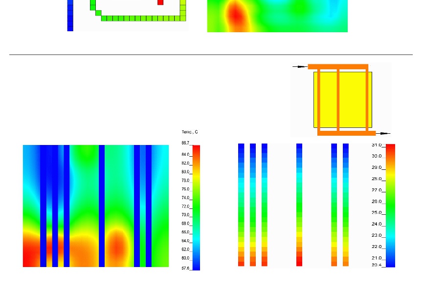
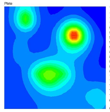
After selecting the final design or as part of the selection process, the temperature on the base plate (or fluid) can be displayed along
with the applied power dissipation as shown in the images below.
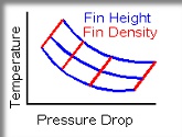
A large selection of fin types are already built into the program fin
type library, these include rectangular, wavy, triangular, lanced
and offset as well as staggered or inline pin fins. The built in
library fins are from Kays and London's book, Compat Heat
Exchangers. Do you have propriatary f and j curves (Fanning and
Colburn), no problem, there is a user defined fin type file
(fintype.dta) to add all your own f and j curves and build your own
libary.
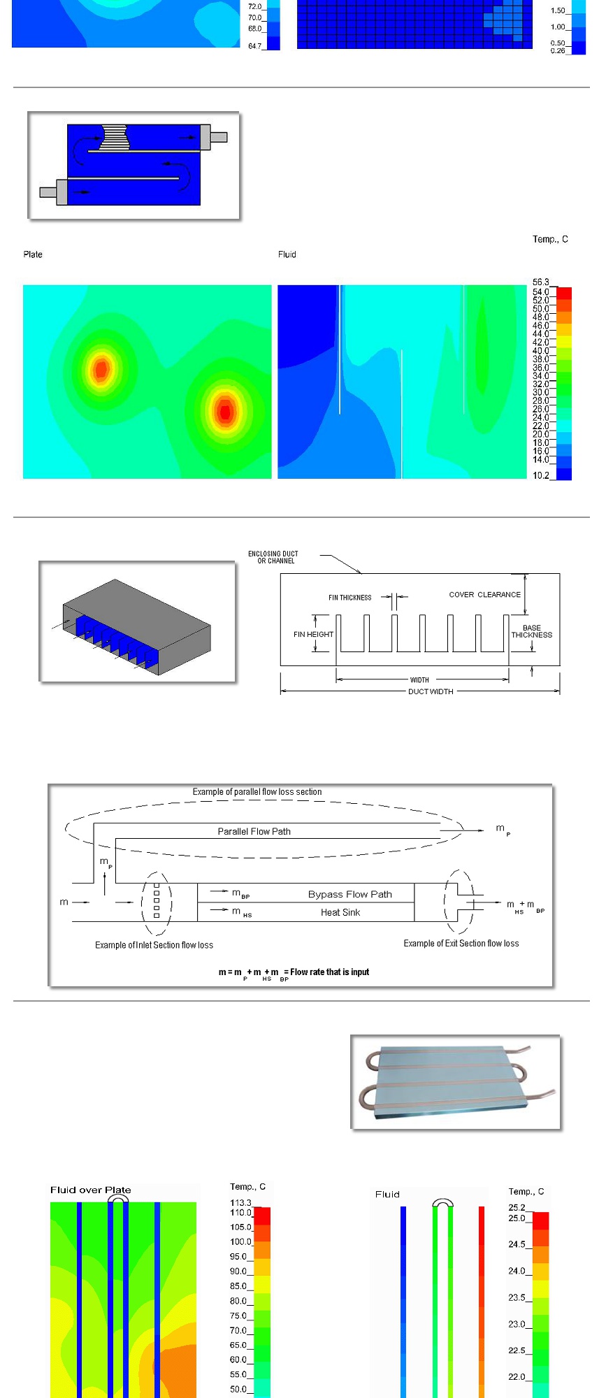
The finned serpentine model has all the capability of the Flow Through Finned
cold plate model but with the addition of a single new parameter, that is, of
the number of passes. With this single new value, the model becomes a
serpentined cold plate with any number of passes. The image shown at the
left has 3 passes (1 path). This type of model is typically for liquid cooling but
it can also be air. Shown below is a 4 pass model. Changing the model from a
3 pass model to a 4 pass model is as simple as changing a 3 to a 4.
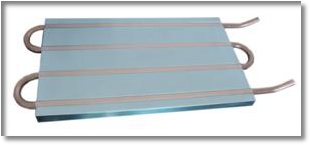
A heat sink located in a duct or channel with air forced through it may be modeled using COLDPLATE's bypass capability. The model is
built just like the other models but in this case the Duct Width and Cover Clearnce are also inputted. Both of these parameters, like
many other parameters, can have multiple values within the same model to optimize the design. As with all models, fluid flow that is in
parallel or in addition to the cold plate or heat sink can be a account for by specifying the duct size, length or equivalent loss coefficient
of the parallel path or inlet and/or exit sections
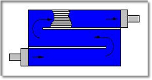
Extended multi-pass tubed models primarily for liquid cooling are easily built by
specifying the number of passes. Just indicate which node row number the pass
is attached to, its diameter or cross-section height and width and its thermal
resistance to the base plate. The passes do not have to be equally spaced.
Liquid cooled cold plates with tubes clamped, swagged, adhered, machined
into, or otherwise attached can be modeled. As with all models, the pressure
drop parameters for quick disconnects, turns, etc. prior to and after the cold
plate can also be included in the model. The extended part of the tube is
assumed not to participate in heat transfer to the base plate except in its
detemination of its heat transfer coefficient. However, the toal length including
the extensions are included in the pressure drop calculations.
Un-Extended Multi-Pass Tube Model
Custom Multi-Pass Tube Model
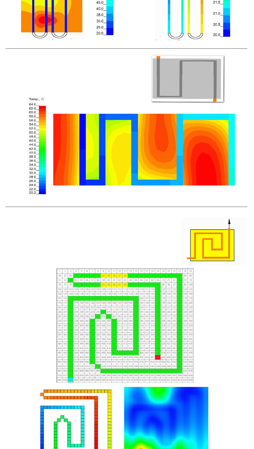
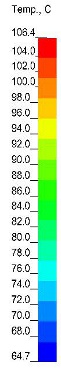
If you have a non-standard single path design but with a user defined layout, the custom multi-pass
layout model will handle your requirements. The flow path can be very quickly laid out (routed) with
lots of flexibility. The inlet and exit can be anywhere on the cold plate, and the tube (or channel) can
be easily defined to route over an obstruction such as a bracket or component. In the model below,
the fluid inlet is shown in blue at the lower left, the exit in red is withn the plate in this example and
the tube section in yellow is where the tube is not attached to the plate but is continuous. The model
below took less than ten minutes to built from start to dispay of results. As in all models, the tube
diameter, base thickness, fluid type, flow rate, etc. (Variable Analysis Capability) can changed within
the same model run without have to make other changes. In addition, this variable analysis can be
viewed as a case number (animated) plot if you wish.
Multi-Path Model
With the multi-path model, you can simulate a number of tubes or channels that flow from
inlet header to exit header. It is assumed that both the inlet and exit header is designed or
large enough so that the flow is equal in each branch. As with the other tube/channel
models, the tube spacing does not need to be equal between tubes.
Copyright 2019 epac-inc.com